Home » Engineering » mechanical engineering » Mastering the Art of Lathe in Mechanical Engineering: A Comprehensive Guide

Comprehensive Guide of the Art of Lathe in Mechanical Engineering

Introduction

The lathe stands as one of the oldest machine tools and earns the title "mother of machine tools" because it serves as the foundation for all other machine tools. Operators can perform a variety of cutting operations on a lathe, with or without additional attachments. The lathe rotates the workpiece while moving the cutting tool in a straight line. Manufacturers classify lathe machines based on their speed and application. In this blog, we will explore the classification, components, and functions of the lathe in detail.

Diagram of a lathe machine with labeled dimensions A through E. A gradient background shifts from orange to blue, conveying a technical and educational tone.

Classification of Lathes

According to the construction and design lathe can be classified as follows:
  1. Bench Lathe: This small lathe mounts on a separate table and includes all the attachments found on larger lathes. Operators use it to perform precise work.
  2. Speed Lathe: This lathe may come as a bench type or one supported by legs. It lacks a gearbox, carriage, and lead screw, so the operator moves and feeds the tool by hand. People use this lathe for wood turning, polishing, and spinning.
  3. Engine Lathe: This lathe remains the most widely used type. During the lathe’s early development, steam engines powered it, which is why people call it an engine lathe. Today, manufacturers equip engine lathes with separate engines or electric motors. Operators achieve various speeds by using cone pulleys and gears.
  4. Tool Room Lathe: This lathe closely resembles an engine lathe but includes extra attachments for more accurate and precise work. Common attachments include taper turning devices, follower rests, collets, and chucks.
  5. Capstan and Turret Lathes: These semi-automatic lathes perform a wide range of operations. They hold many more cutting tools than an engine lathe.

Functions and Components of a Lathe

A lathe is a versatile machine tool that primarily functions by rotating a workpiece on its axis while a cutting tool removes material. To begin with, it's essential in shaping cylindrical parts. Moreover, it supports turning, facing, and threading. In fact, its flexibility suits many industries. Consequently, it enhances precision. Additionally, both manual and automated types exist. As a result, productivity improves. In comparison, manual lathes need more skill. Furthermore, CNC lathes offer efficiency. Therefore, complex tasks are easier. Likewise, output quality increases. Notably, alignment is key. Otherwise, errors arise. For instance, poor centering affects tolerance. Next, follow safety rules. Meanwhile, choose the right tool. In contrast, dull tools reduce quality. Eventually, maintenance is vital. Hence, inspections matter. Also, lubrication helps. In other words, upkeep ensures performance. Key parts include the bed, headstock, tailstock, carriage, and lead screw:
  • Bed: Supports all major components.
  • Headstock: Holds the jaws for the workpiece,supplies power to the jaws and has various drive speed.
  • Tailstock: Support the other end of the workpiece.
  • Carriage: Slides along the ways and consists of the cross-slide,tool post,apron.
    1. Cross Slide: The operator mounts the cross slide on the carriage. It moves the cutting tool 90° to the workpiece.
    2. Apron: The apron contains the control and the gear that allow you to move the carriage and cross slide.
    3. Tool Post: The tool post support and secure the cutting tool or tool holder.

Importance in Modern Manufacturing

The lathe machine remains a fundamental tool in manufacturing for several reasons:
  • Precision Machining: Lathes produce highly accurate and symmetrical parts, making them indispensable in industries that require precision.
  • Versatility: From simple operations like turning and facing to more complex tasks like threading and profiling, lathes can handle a wide range of machining operations.
  • Customization: Modern CNC (Computer Numerical Control) lathes have revolutionized customization, allowing manufacturers to create unique and complex components with ease.
  • Mass Production: Lathes are also essential for mass production, enabling the rapid and consistent production of standardized components.
  • Education and Training: Lathes play a significant role in training future machinists and engineers, helping them understand the fundamentals of machining.

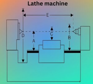
Specifications of Lathe

Lathe machine can be specified by following dimensions (Figure 1):
A technical diagram of a cross-sectional mechanical component with labeled measurements A, B, C, D, and E. Arrows indicate dimensions.
Figure 1
  • Height of centre over bed (A).
  • Maximum swing over bed (B).
  • Maximum swing over carriage (C).
  • Maximum swing in gap (D).
  • Maximum length of work (E).

Constructional Detail of Lathe

Typically, a lathe machine has many components. These parts perform key functions; for example, they firstly vary speed, secondly hold the tool, and thirdly secure the job. Moreover, they support the job’s end and enable tool movement. Consequently, operations run smoothly. Furthermore, their roles are linked. In fact, alignment ensures precision. Similarly, design reduces vibration. On the other hand, poor setup affects output. Therefore, understanding parts is vital. Eventually, this aids maintenance. Meanwhile, performance improves. In contrast, neglect causes damage. As a result, downtime increases. Thus, placement matters. Notably, small parts count. Besides, each adds efficiency. Likewise, all boost safety. Above all, accuracy depends on setup. Ultimately, efficiency reflects design. A lathe, with this in mind, is shown in Figure 2.
 
Bed: The lathe operator mounts all fixed and moving parts on the bed. Manufacturers typically cast the bed in a single piece of cast iron, but for large lathes, they make it in two or three pieces bolted together. The bed includes V-ways that collect chips produced during machining.
 
Head Stock:Head stock is housing of cone pulleys, back gear, main spindle, live centre, and feed reverse livers. It provides driving mechanism to the job and tool post, carriage, apron, etc.
Diagram of a lathe machine with labeled parts including headstock, tailstock, spindle, tool post, bed, carriage, lead screw, and handwheel.
Figure 2
Cross-sectional diagram showing labeled parts of a lathe tailstock, including tailstock center, clamping lever, spindle, spindle screw, hand wheel, quill, and clamping nut.
Figure 3

Tail Stock: The tail stock supports the job at the end and slides along the bed. It may hold a dead center or a live center to provide point support, depending on the requirement. Figure 3 shows a tail stock. For tapping, drilling, or boring, the operator replaces the dead center with a tap or drill/boring tool. The operator moves the dead center forward or backward by manually rotating the hand wheel on the sleeve.

Carriage and Tool Post: It provides support to the tool post, cross slide, compound rest, apron, etc. The function of tool post is to hold cutting tool rigidly; tool post moves in both axial and transverse directions on compound rest. The function of swivel plate is to give angular direction to the tool post whereas the function of cross slide is to give the linear motion to the tool by rotating the attached hand wheel. Apron is a hanging part in front of the carriage. It is housing of gear trains and clutches. It gives automatic forward and reverse motion to the tool.

Legs: The legs provide rigid support to the entire machine tool. Operators firmly secure both legs to the floor using foundation bolts to prevent vibrations.

Chucks: The chuck holds the job securely. It may have three or four jaws, as shown in Figure 4. In a three-jaw chuck, all jaws move inward or outward simultaneously, making centering easy—this is why people also call it a universal chuck. In contrast, each jaw in a four-jaw chuck moves independently. This design can hold irregularly shaped jobs but requires manual centering. Operators also use magnetic chucks, which hold the job using the principle of electromagnetism.

Two metallic chuck diagrams are shown: one is a 3-jaw self-centering chuck, and the other is a 4-jaw independent chuck. Removable jaws are labeled.
Figure 4

Power Transmission System in Lathe Machine

The headstock spindle drive system may use either a stepped or cone pulley drive, or an all-geared head drive. In a stepped pulley system, the operator selects speeds equal to the number of steps on the pulley. An all-geared head drive allows the operator to achieve nine different speeds.
 
Stepped Pulley (Cone Pulley) Drive: V-belt is used to transmit the power from driver shaft to spindle shaft. In four-stepped pulley drive, four different speeds of the head stock can be attained. Spindle speeds are varied in arithmetic progression (Figure 5).
Diagram of a gear mechanism with two parallel driver shafts, each supported by bearings. Gears N1 to N4 are aligned between the shafts.
Figure 5

Let driver shaft rotates at the speed of N rotation per minute (rpm) and the stepped diameters of the pulley are `D_1`,`D_2`,`D_3` and `D_4`.Driven shaft has pulley of same steps diameters but in
reverse order as shown in Figure 5. We know the speed is inversely proportional to the diameter, therefore,

`frac{N_1}N`=`frac{D_4}{D_1}`;`frac{N_2}N`=`frac{D_3}{D_2}`:`frac{N_3}N`=`frac{D_2}{D_3}`;`frac{N_4}N`=`frac{D_1}{D_4}`
where N is speed of driver shaft and `N_1`,`N_2`,`N_3` and `N_4` are speeds of spindle shaft.
Here `D_1` < `D_2` < `D_3` < `D_4`.

All Geared Head Drive

This drive includes nine gears mounted on three shafts. The operator controls two levers connected to cluster gears on the pulley shaft and the headstock main spindle to select nine different speeds. Three gears (2, 4, and 6) remain fixed on the intermediate shaft. The operator fixes spur gear 10 on the headstock spindle to transmit power to the feed shaft and lead screw. Figure 6 shows the detailed construction of the geared head drive.
Diagram illustrating a mechanical system with interconnected rods numbered 1 to 10. Bearings are labeled on the sides. Technical and precise tone.
Figure 6
The gear combinations for nine different speeds are given below:
`frac{T_1}{T_2}`×`frac{T_2}{T_7}`;`frac{T_1}{T_2}`×`frac{T_4}{T_8}`;`frac{T_1}{T_2}`×`frac{T_6}{T_9}`
`frac{T_3}{T_4}`×`frac{T_2}{T_7}`;`frac{T_3}{T_4}`×`frac{T_4}{T_8}`;`frac{T_3}{T_4}`×`frac{T_6}{T_9}`
`frac{T_5}{T_6}`×`frac{T_2}{T_7}`;`frac{T_5}{T_6}`×`frac{T_4}{T_8}`;`frac{T_5}{T_6}`×`frac{T_6}{T_9}`
where `T_1`,`T_2`,`T_3`,`T_4`,`T_5`,`T_6`,`T_7`,`T_8` and `T_9` are number of teeth on gear 1, 2, 3, 4, 5, 6, 7, 8 and 9 respectively.

Cutting Tools Used in Lathe

A number of cutting operations are performed on a lathe machine. Therefore, various cutting tools are used in lathe such as left-hand and right-hand turning tools, facing tools, threading tools, parting-off tool, etc., as shown in Figure 7.

A diagram shows seven types of turning tools: left hand, round nose, right hand, left hand facing, threading, right hand facing, and parting tool.
Figure 7

Types of Operations on Lathe Machine

Following are the various types of operations performed on the lathe machines.

Turning

Turning is a metal removal process in which job is given rotational motion while the cutting tool is given linear (feed and depth of cut) motion.Different types of turning operations are mentioned as follows:

Straight Turning

It is the operation of producing a cylindrical surface of a job by removing excess material. In this operation, the job rotates and tool is fed longitudinally by giving the desired depth of cut (Figure 8). 
Diagram of a cylindrical workpiece being machined on a lathe. A single-point cutting tool removes a chip, showing the original and new surfaces.
Figure 8
Face Turning or Facing: Face turning is also known as facing operation. It is the operation of making the ends of a job to produce a square surface with axis of operation or to make a desired length of the job. In this operation job rotates and the tool advances in perpendicular direction to the axis of the job rotation (Figure 9).
Diagram of a lathe setup showing a chuck holding a cylindrical job. The tool is poised for cutting, with arrows indicating motion and positions.
Figure 9

Shoulder Turning

If a job is turned with different diameters, the steps for one diameter to the other so formed, the surface is known as shoulder turning. There are several types of shoulder turning such as square, radius, bevelled, etc., as shown in Figure 10. It is also known as step turning.

Diagram illustrating three types of shoulders in machining: square, beveled, and radius. Each has distinct angles at the edge where it meets the cylindrical part.
Figure 10

Eccentric Turning

When a job having more than one axis of rotation, each axis may be parallel with each other but never coincides; turning of different cylindrical surfaces of the job is known as eccentric turning. In Figure 11, the job is first turned through centres `C_1`-`C_1` and then through centres `C_2`-`C_2`.
 

Taper Turning

Taper turning is an operation in which taper cylindrical surface, i.e.,cone type surface is produced as shown in Figure 11.
Diagram showing a horizontal cross-section of a rectangular object with two channels labeled C1 and C2, shaded area on left, conveying intersecting paths.
Figure 11
A simple line diagram of a horn antenna, showing dimensions D_i and D_s at the wide and narrow ends, with a labeled "Feed" pointing to the narrow end.
Figure 12
Taper on a cylindrical surface of a job can be produced by the following methods:
  • Taper turning by swivelling compound rest: Job rotates on lathe axis and tool moves on angular path. It can be applied from any angle `0^circ`-`90^circ` for short length of taper up to 150 mm (approximate) `tanleft(alpharight)`=`frac{D_1-D_S}{2l}`.It is used for shorter length and steeper angle. Here,`D_1` and `D_S` are larger and shorter diameters, l is length of the job, and is angle of taper.
  • Taper turning by off-setting the tailstock: Job rotates at an angle to the lathe axis and the tool travels longitudinally to the lathe axis. Any angle 0° – 8°, long job of smaller diameter can be turned by this method. It is also used for internal taper turning.
  • Taper turning attachment: Job rotates on lathe axis and tool moves in guided angular path. Long jobs of steeper angle of taper (0° – 12°) can be done by this attachment. Guide rail is set as per angle of taper. It is applied for mass production.
  • Taper tuning by a form tool: Job rotates on lathe axis and tool moves crosswise direction,perpendicular to the lathe axis. Very small length of taper and any angle 0° – 90°.Tool itself designed as per requirements. It is used for mass production for Chamfering on bolts, nuts, bushes, etc.
  • Taper turning by combination fed: Job rotates on lathe axis and tool travels on resultant path, for any length and any angle. Taper angle is to be determined by trial and error method.It is applied by hand feeds by combined feeding of tool (axial and perpendicular) for taper turning.

Parting-off (Grooving)

Parting-off (or grooving) cuts off a bar after machining it to the required shape and size. The operator holds the job in a chuck and rotates it at turning speed. Then, they feed the parting-off tool slowly into the job until the tool reaches the center. Figure 13 shows the parting-off operation.
Diagram illustrating the parting-off process on a lathe. Labeled elements include a chuck holding the job and the parting tool cutting into the material.
Figure 13

Knurling

Knurling is the process of embossing that creates a roughened surface on a smooth cylindrical job to provide effective gripping—for example, on the thimble and ratchet of a micrometer or the handle of a plug gauge. During knurling, tools (which may have single, two, or three sets of rollers) are held rigidly on the tool post and pressed against the rotating surface of the job, which turns at one-third the speed of the tool. This action leaves an exact facsimile of the tool’s pattern on the job’s surface, as shown in Figure 14.
Diagram of a lathe setup: a workpiece held in a chuck, cross-hatched for grip, with an arrow indicating tool movement direction. Labeled "Workpiece."
Figure 14

Thread Cutting

For thread cutting on the lathe, there is definite relationship between the speeds of the job and tool. The relationship is obtained by gear ratio selection which depends on the pitch of the job, pitch of the lead screw, number of start of thread on the job. Every machine is supplied with a spur gear box (a set of 23 gears) having teeth from 20 to 120 with an interval of 5 and a special gear or transfer gear is of 127 teeth for cutting metric thread. Two 20 teeth spurs are available. Lead screw has single start thread. The simple process of thread cutting on lathe is shown in Figure 15.
Schematic of a turning process, showing a tool cutting threads on a rotating workpiece. Arrows indicate rotation and tool movement. Technical and precise.
Figure 15

Steps for Thread Cutting on Lathe

  1. Hold the job on machine and turn up to major diameter of the thread.
  2. Choose suitable thread cutting tool.
  3. Select slower speed of the lathe spindle.
  4. Calculate the change gear ratio based on the following formula:

Change gear ratio=pitch of the job×No. of startPitch of the lead screw

  1. Fix the calculated change gear ratio to the head stock spindle, intermediate shaft, and lead screw shaft.
  2. Choose suitable depth of cut. Three or four cuts are necessary to complete the thread.
  3. Arrange job and tool proper position and give desired depth of cut.
  4. Engage half nut with respect to chasing dial according to odd/even threads.
  5. Allow the movement of the tool up to the portions of the job necessary for thread cutting
    then lifting the tool from the job.
  6. Disengage the half nut, move the carriage to the right side up to the position from where
    second cut will start. Allowing the second depth of cut again engages the half nut with
    respect to chasing dial.

Drilling

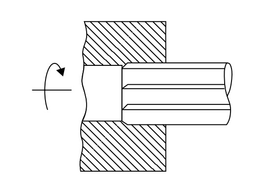
Generally, drilling forms a circular hole by rotating the tool. However, in a lathe, the drill remains static, and the job rotates via the tailstock feed. Consequently, metal is removed through shearing and extrusion. In most cases, holes become slightly oversized because of misalignment or vibration. Therefore, an undersized drill is preferred. Subsequently, in addition, reaming or boring ensures accuracy. Furthermore, alignment boosts precision. Nevertheless, improper setup causes defects. On the other hand, careful setup prevents issues. In contrast, poor setup affects hole shape. Moreover, choosing the right bit is essential. In other words, each step impacts accuracy. As a result, holes meet required standards. Besides, vibration control is crucial. Likewise, rigid setup helps. To clarify, drill depth must match the hole. Also, proper lubrication aids performance. Eventually, the drill reaches final depth, as shown in Figure 16. Ultimately, accuracy depends on the entire process.

Diagram showing a drill bit partially inserted into a material block. The material is hatched, indicating cross-section, with an arrow pointing leftward.
Figure 16

Drilling on a lathe is a straightforward process. The operator holds the drill bit in the tailstock, replacing the dead center, and moves it forward while applying pressure to the end of the rotating job.

Tapping

Tapping creates internal threads in a drilled hole. First, the operator drills a hole of the required minor diameter by holding the drill tool in the tailstock and applying pressure to the rotating job in the chuck. After drilling, the operator mounts the tap in the tailstock and inserts it into the drilled hole of the rotating job, as shown in Figure 17.
Diagram of a lathe machine highlighting components: "Chuck," "Job," "Tool," and "Tail stock end." Labels indicate parts and function. Simple black-and-white style.
Figure 17

Reaming

Reaming finishes and sizes a previously drilled hole using a straight, multi-edged cutting tool called a reamer. This operation removes a very small amount of material—typically around 0.4 mm. On a lathe, reaming closely resembles drilling, as shown in Figure 18.
Cross-section diagram of a keyed shaft and hub assembly showing mechanical engagement. An arrow indicates rotational movement. Technical illustration style.
Figure 18

Boring

Boring enlarges and finishes a previously drilled hole along its entire length using an adjustable single-edge cutting tool called a boring tool. This operation, typically performed on a lathe, closely resembles drilling. However, instead of creating a new hole, boring enlarges the existing one, as shown in Figure 19.
Diagram of a lathe showing a workpiece being machined. It depicts a turning operation, with an arrow indicating rotation and another showing feed direction.
Figure 19

Spinning

Spinning produces circular, homogeneous pots or household utensils by shaping sheet metal. In this process, the operator holds the sheet metal between a former mounted on the headstock spindle and the tailstock center, then rotates it at high speed along with the former. A long, round-nose forming tool, fixed rigidly to a special tool post, presses the metal against the periphery of the former, as shown in Figure 20. This pressure deforms the sheet metal to match the exact shape of the former, completing the spinning operation. Spinning is a chipless machining process.
Diagram of spin forming: a metal sheet wraps around a rotating former, with a forming tool pressing and moving toward the tailstock. Labels indicate parts.
Figure 20

Conclusion

The lathe machine is not as simple as it was and it is today a complex machine that helps produce various produces. It is not surprising that it is a foundation of industries, in a wide field of application such as aerospace and automotive, electronic technologies of medicine, electronics and healthcare. The skilled hands of the lathe operators mold the world and propel, innovation still serves as a testimony of the multifaceted importance skill and technology has brought to human society.

Share

Leave a Reply